[Prev][Next]
Cozy MKIV - Chapter 23
Installing the Engine
Start Date: February 17, 1999
 This photograph shows a top view of the
throttle quadrant installation with the CableCraft throttle cable for the Ellison throttle
body injector. You can also see the hydraulic damper for the landing brake. I
had to modify the small aluminum angle bracket used to secure the three cables to the
sides of the channel to clear the motion of the damper. You can just see the bracket
to the right of the brake handle axle.
I purchased my engine from AeroSport Power in Kamloops, BC. They shipped an O-360
A2A (solid crank) with two mags and a lightweight starter (Skytec). The engine looks
great, and I've only heard good things about them from others who have purchased their
engines. They certainly have good customer relations, and I like their
responsiveness to my phone calls and letters.
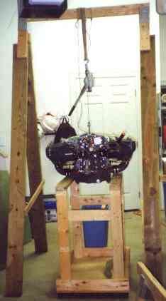
 Here you can see both the engine hoist and the engine
stand that I built. The stand followed the plans exactly, and works great. I
built the hoist from a horse, and screwed some 2" x 6"'s to it to extend the
legs. I screwed some cross pieces on to stabilize it, and then dragged the engine on
the pallet under the hoist. I used my comealong to lift the engine off the hoist and
place it on the stand. One person, four hours total work to build both and get the
engine in place. No strained backs, no lifting whatsoever.
Next, I replaced the stock oil screen housing with a B&C right angle oil filter
adapter. This allows me to use an oil filter in the cramped area between the engine
and the firewall. I also installed the vacuum pump onto the vacuum pump pad.
Next, I fabricated the mixture cable bracket and installed it and the Ellison throttle
body to the sump. I purchased an 8" prop extension from Judy Saber and bolted
it onto the flywheel/ring gear.
I mounted the engine mount to the firewall per plans, drilling holes through the
firewall hardpoints and ensuring that the mount stayed level and straight. I had to
install a 4 BID pad under the upper left mount pad due to a minor unevenness.
Per plans, I hot-glued urethane foam to the firewall and carved it to the shape of the
fuselage, covering it with box sealing tape. I then laid up 4 BID over it onto the
fuselage for the cowling rim.
Then I bolted the engine mount (from AeroCad, fabricated by RANS) to the engine and
bolted the mount to the firewall. I kept the engine stand under the engine at all
times to protect against tip-over, although without the wings in place the plane still has
at least 50 lbs. on the nose gear.
 I began the cowling installation, which
went pretty much per plans. Since my main spar ended up 3/8" low, I had to do a
bit of patching of the lower cowls to get things to line up, but it wasn't a real big
deal. I also had to cut a few holes that will need minor patching in the lower cowl
to clear the intake pipes. Other than that, the cowling installation went smoothly.
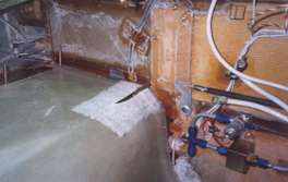
In this picture, you can see the area of the bottom cowl where I had to patch it.
You can also see the vent lines along the main spar just above the patch area, as
well as all the fuel lines, wiring, and control pushrods temporarily fitted to the
firewall.
After finishing the cowling installation with the left wing, I shifted to Chapter 15 to finish the firewall, and then came back to
Chapter 23.
After continuing with a lot of the baffling work (ha, ha, make your jokes) I discovered
that the engine mount that I had purchased from AeroCad had been make incorrectly -
positioning the engine about 1.25" too low. See "The Last Oaf's Story" for a full accounting
of this issue.
While waiting for the new engine mount (from AeroCad, fabbed by Velocity) to arrive, I
continued with the stiffeners/baffles in the top and bottom cowlings, as well as the
cowling flanges. I finished fabricating the air box, carb. heat/cabin heat Tee and
cabin heat valve. I fabricated new 1/8" exhaust pipe supports to replace the
1/32" originals (the new ones contribute strength dictated by the failure of a
support to keep a broken exhaust pipe from destroying someone's propeller and causing a
forced landing). I also fabricated the oil filler door in the top cowling.
I purchased what have GOT to be the most expensive fuel lines in the
known universe - the three of them (to go from the electric fuel pump to the mechanical
fuel pump to the fuel filter to the Ellison throttle body) ended up costing about $350,
and the two oil lines were about $250 (twice, as it turns out, since I had to move the oil
cooler after getting a correct engine mount - I now have $250 of useless oil lines).
They are all stainless braided teflon with integral firesleeve, and I'm sure they'll last
forever, but it would have saved me a LOT of money to just use standard
hoses and replace them ALL every year during the conditional
inspection.....
 In this picture you can see the oil cooler
(sans bazillion dollar oil lines) mounted in the bottom right cowl (just like Nat's, I
believe). You can see the heat muff next to it, with the SCAT tubing running to the
carb heat/cabin heat, and the cylinders with baffling.
End Date: June 21, 2001
[Prev]
[Next]
Copyright © 1999 - 2001, All Rights Reserved, Marc J. Zeitlin
e-mail: marc_zeitlin@alum.mit.edu
 This photograph shows a top view of the
throttle quadrant installation with the CableCraft throttle cable for the Ellison throttle
body injector. You can also see the hydraulic damper for the landing brake. I
had to modify the small aluminum angle bracket used to secure the three cables to the
sides of the channel to clear the motion of the damper. You can just see the bracket
to the right of the brake handle axle.
 Here you can see both the engine hoist and the engine
stand that I built. The stand followed the plans exactly, and works great. I
built the hoist from a horse, and screwed some 2" x 6"'s to it to extend the
legs. I screwed some cross pieces on to stabilize it, and then dragged the engine on
the pallet under the hoist. I used my comealong to lift the engine off the hoist and
place it on the stand. One person, four hours total work to build both and get the
engine in place. No strained backs, no lifting whatsoever.
 I began the cowling installation, which
went pretty much per plans. Since my main spar ended up 3/8" low, I had to do a
bit of patching of the lower cowls to get things to line up, but it wasn't a real big
deal. I also had to cut a few holes that will need minor patching in the lower cowl
to clear the intake pipes. Other than that, the cowling installation went smoothly.
In this picture, you can see the area of the bottom cowl where I had to patch it.
You can also see the vent lines along the main spar just above the patch area, as
well as all the fuel lines, wiring, and control pushrods temporarily fitted to the
firewall.
 In this picture you can see the oil cooler
(sans bazillion dollar oil lines) mounted in the bottom right cowl (just like Nat's, I
believe). You can see the heat muff next to it, with the SCAT tubing running to the
carb heat/cabin heat, and the cylinders with baffling.