[Prev]
[Next]
Cozy MKIV - Chapter 22
Installing the Electrical System
Start Date: August 16, 1997
The first thing anyone doing an aircraft electrical system should do is buy the book "The AeroElectric Connection"
written by Bob Nuckolls. It runs
about $35 and has excellent descriptions of all the aspects of aircraft electrical
systems.
After reading this, I spent about 15 hours over the course of a couple of weeks drawing
circuit diagrams of the Master Bus, Essential Bus, gear/canopy/throttle
alarm system, and battery/engine/starter/ground wiring. I tried to combine the
electrical system as described in the plans with the general info in "The AeroElectric Connection". I
made a list of all the parts I would need from Radio
Shack, Digikey, Nuckolls himself, Wicks Aircraft and B&C
Industries (information provided in "The
AeroElectric Connection").
First, I made a shielded wire harness for the 4-place stereo intercom system. I chose
to mount the jacks for the headsets and microphones in the shoulder support between the
headrests (for the front) and in the vertical pillar between the rear seats for the rear
passengers. This meant that the harness would have a length of approximately ten feet. I
routed it inside the shoulder support and down the front seatback to the right side
electrical conduit. After fixing one short in a microphone cable and using a motorcycle
battery to power the electrical system rather than the battery charger I had used, I got
the intercom to work perfectly.
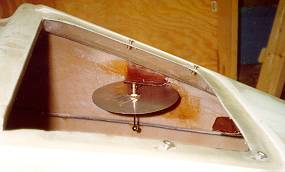 I next made a ground plane
from 0.032" aluminum cut into an octagon (easier than making a circle) approximately
12 inches across. I bent up four of the edges to increase the stiffness, drilled a hole in
the center for the antennae I bought from Aircraft Spruce, and then created some tabs to
hold the antennae in place in the nose of the fuselage in front of the pilot side rudder
pedals. I created a tower and a tab on the center nose gear cover, as well as one on the
fuselage side and on the fuselage top just under the large door. The tabs on the fuselage
sides contain the antenna ground plane on the top and bottom, while a short sheet metal
screw holds the antenna onto the tower tab. As it turned out, I SHOULD have made
the antennae 5.63 inches in diameter, so I cut it down to this size and then remounted it
in the one tab visible here.
I next made a ground plane
from 0.032" aluminum cut into an octagon (easier than making a circle) approximately
12 inches across. I bent up four of the edges to increase the stiffness, drilled a hole in
the center for the antennae I bought from Aircraft Spruce, and then created some tabs to
hold the antennae in place in the nose of the fuselage in front of the pilot side rudder
pedals. I created a tower and a tab on the center nose gear cover, as well as one on the
fuselage side and on the fuselage top just under the large door. The tabs on the fuselage
sides contain the antenna ground plane on the top and bottom, while a short sheet metal
screw holds the antenna onto the tower tab. As it turned out, I SHOULD have made
the antennae 5.63 inches in diameter, so I cut it down to this size and then remounted it
in the one tab visible here.
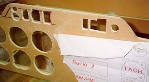
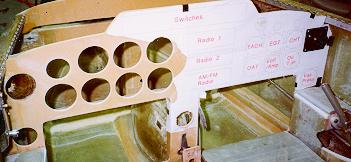 I layed out my instrument panel in my CAD system at work,
and then plotted it out. After a couple of iterations of this, ensuring that all the
existing holes (cabin air vents) and features lined up with the plotted template, I taped
the template to the instrument panel and began cutting holes with 3 1/8" and 2
1/4" hole saws. You can see the holes for the eight main instruments, as well as a
couple of auxiliary ones in the side panel just above the left armrest as well as in the
center console above the roll trim lever.
I layed out my instrument panel in my CAD system at work,
and then plotted it out. After a couple of iterations of this, ensuring that all the
existing holes (cabin air vents) and features lined up with the plotted template, I taped
the template to the instrument panel and began cutting holes with 3 1/8" and 2
1/4" hole saws. You can see the holes for the eight main instruments, as well as a
couple of auxiliary ones in the side panel just above the left armrest as well as in the
center console above the roll trim lever.
The template shows the layout for the center radio stack, as well as for the analog
engine instruments on the right side.
 |
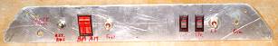
I made a switch/light mounting plate for the top center of the instrument
panel from 1/16" aluminum. I laid out the necessary switches, lights and breakers on
this panel and drilled or cut out holes as necessary for mounting them, as well as holes
for mounting the plate to the instrument panel. I then cut holes in the top of the
instrument panel to clear all the components sticking through the back side of the switch
panel. I've also mounted the key/mag/start switch in the center of this switch panel, as
well as an ON-OFF switch for the Navaid autopilot. |
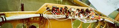 Here you can see the back side of the switch plate with all
switches installed and most of the wiring run.
Here you can see the back side of the switch plate with all
switches installed and most of the wiring run.
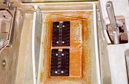 This picture shows the
master, essential, and ground busses under the copilot seat. I glassed a 1/4" plywood
sheet in place to which to screw the busses. I bought the 14 slot master and essential
fuse busses from J.C. Whitney, and the ground buss (all Fast-On tab busses) from B&C.
This picture shows the
master, essential, and ground busses under the copilot seat. I glassed a 1/4" plywood
sheet in place to which to screw the busses. I bought the 14 slot master and essential
fuse busses from J.C. Whitney, and the ground buss (all Fast-On tab busses) from B&C.
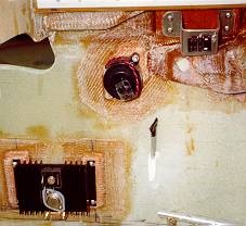 I mounted the warning relay on a small sheet metal bracket I bent up
from 1/16" aluminum just under the longeron behind the instrument panel on the
co-pilot's side. I then floxed and glassed small 1/4" thick plywood strips to the
fuselage side to which to screw the relay bracket, the dimmer circuit and master/essential
buss diode bridge heatsink, as well as the warning circuit piezo buzzer (dual tone, like
the backup horn on trucks). To orient yourself, you can see the cutout for the elevator
torque tube and F-22 near the top left of the picture.
I mounted the warning relay on a small sheet metal bracket I bent up
from 1/16" aluminum just under the longeron behind the instrument panel on the
co-pilot's side. I then floxed and glassed small 1/4" thick plywood strips to the
fuselage side to which to screw the relay bracket, the dimmer circuit and master/essential
buss diode bridge heatsink, as well as the warning circuit piezo buzzer (dual tone, like
the backup horn on trucks). To orient yourself, you can see the cutout for the elevator
torque tube and F-22 near the top left of the picture.
I ran wires back through the conduits for the strobe and navigation lights, as well as for
the magnetos, fuel pump, and primer.
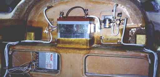 Here you can see the wiring over the main spar in the
rear of the aircraft, as well as the strobe power supply in the spar cavity. I have
positioned a Concorde RG25 battery pretty much dead center, and built a glass surround for
it. A 1/16" aluminum strap bolted to the firewall ensures that the battery
cannot move. Two rubber feet on the firewall and on the rear of the strap front
ensure that the battery will not vibrate against anything solid. The rear ground bus
attaches to the firewall to the left of the battery, while the battery solenoid and
ammeter shunt attach to the firewall to the right of the battery. I used #4 cable
from the battery to the ground and master busses in the front and rear, and #2 cable to
the solenoid and continuing on to the starter connections. Two holes through the firewall
allow power and ground cables to connect to any engine connection without having to route
down through the electrical conduits. I will seal these holes (as with all firewall
holes) with high temperature RTV Silicone.
Here you can see the wiring over the main spar in the
rear of the aircraft, as well as the strobe power supply in the spar cavity. I have
positioned a Concorde RG25 battery pretty much dead center, and built a glass surround for
it. A 1/16" aluminum strap bolted to the firewall ensures that the battery
cannot move. Two rubber feet on the firewall and on the rear of the strap front
ensure that the battery will not vibrate against anything solid. The rear ground bus
attaches to the firewall to the left of the battery, while the battery solenoid and
ammeter shunt attach to the firewall to the right of the battery. I used #4 cable
from the battery to the ground and master busses in the front and rear, and #2 cable to
the solenoid and continuing on to the starter connections. Two holes through the firewall
allow power and ground cables to connect to any engine connection without having to route
down through the electrical conduits. I will seal these holes (as with all firewall
holes) with high temperature RTV Silicone.
Due to weight and balance considerations, I had to move the battery to the nose.
I left the tray in the rear so that it could be mounted in either place, and ran #2
cable up to the nose for the positive line, and connected the battery ground to the front
ground bus.
End Date: July 28, 2002
[Prev]
[Next]
Copyright © 1997 - 2002, All Rights Reserved, Marc J. Zeitlin
e-mail: marc_zeitlin@alum.mit.edu