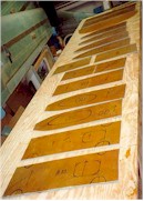
 In this photograph, you can see the raw strake/fuel tank bulkheads. I
cut all the foam and then laid up 1 BID. I cut out the semi-circular baffle slosh areas
and the access holes as required.
In this photograph, you can see the raw strake/fuel tank bulkheads. I
cut all the foam and then laid up 1 BID. I cut out the semi-circular baffle slosh areas
and the access holes as required.[Prev]
[Next] In this photograph, you can see the raw strake/fuel tank bulkheads. I
cut all the foam and then laid up 1 BID. I cut out the semi-circular baffle slosh areas
and the access holes as required.
After installing the spar and the main wing, I started installing Jeff Russell's pre-fab strakes for the COZY MKIV. These molded parts look very nice. The installation procedure differs substantially from that in the COZY manual, so it took me some time to understand the methods to use. First, I cut and fit the strake bottom to match the fuselage side, the spar bottom and the inboard wing end. Then, I marked the strake for the bulkhead positions. I cut and sanded the bulkheads to fit in the strake bottom. Next I sanded the interior of the strake and the front of the spar to fully prepare for a thick layer of epoxy sealer for fuel protection.
I glassed 1 BID over the transition in the strake (from full thickness to glass thickness only, near the tail) and applied the epoxy layer. I peel plied the epoxy layer and and the BID and let it cure. After cutting out the holes in the fuselage sides per plans, I then floxed the strake bottom to the fuselage side and main spar and glassed 2 BID from the strake to the main spar. I also glassed 2 BID on the inner and outer strake/fuselage joints.
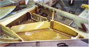 Next, I floxed the ribs into place and glassed them
with 1 BID. The next step involved bending the vent tubing and running these lines.
I installed two 1/4" vent lines (per Carl Denk's suggestions in the COZY
archives). One of these vent lines goes in the standard position while the second one goes
at the top rear of the tank on the front wall of the main spar. This position ensures that
when the plane is parked in the nose down position the tank will still vent. I also
installed a 3/8" return line for any fuel injection system which I might install in
the future. I will cap this line at the firewall, as I plan to install an Ellison
Carb at first. I cut out the 1 1/4" hole for the fuel and then glassed it with
1 BID and a thick epoxy layer. Next, I floxed the aluminum screen over this hole.
I installed the tank drain aluminum pad in the front corner of the tank and then
drilled and tapped it for the drain. I installed a small cripple bulkhead just in
front of this drain, since the prefab strakes carry fuel to the extreme front of the
strake.
Next, I floxed the ribs into place and glassed them
with 1 BID. The next step involved bending the vent tubing and running these lines.
I installed two 1/4" vent lines (per Carl Denk's suggestions in the COZY
archives). One of these vent lines goes in the standard position while the second one goes
at the top rear of the tank on the front wall of the main spar. This position ensures that
when the plane is parked in the nose down position the tank will still vent. I also
installed a 3/8" return line for any fuel injection system which I might install in
the future. I will cap this line at the firewall, as I plan to install an Ellison
Carb at first. I cut out the 1 1/4" hole for the fuel and then glassed it with
1 BID and a thick epoxy layer. Next, I floxed the aluminum screen over this hole.
I installed the tank drain aluminum pad in the front corner of the tank and then
drilled and tapped it for the drain. I installed a small cripple bulkhead just in
front of this drain, since the prefab strakes carry fuel to the extreme front of the
strake.
 The next step involved installing the "T-Hat"
sections. The plans call for just a glob of flox between the top of the bulkheads
and the top strake. While this method has proved itself adequate in innumerable
L.E.'s and Cozys, a method for increasing the contact surface area exists, and I chose to
use it. The archives describe this method, which creates a wide 2 BID layer on top
of each rib. The rib gets a micro/flox layer, while the top strake has 2 BID layed
up on it over box sealing tape and peel ply. After installing the top strake, the BID
layer cures to the micro and when the strake comes off, the BID stays with the ribs.
1 BID under the "T-Hat" connects it to the ribs and gives it more
strength.
The next step involved installing the "T-Hat"
sections. The plans call for just a glob of flox between the top of the bulkheads
and the top strake. While this method has proved itself adequate in innumerable
L.E.'s and Cozys, a method for increasing the contact surface area exists, and I chose to
use it. The archives describe this method, which creates a wide 2 BID layer on top
of each rib. The rib gets a micro/flox layer, while the top strake has 2 BID layed
up on it over box sealing tape and peel ply. After installing the top strake, the BID
layer cures to the micro and when the strake comes off, the BID stays with the ribs.
1 BID under the "T-Hat" connects it to the ribs and gives it more
strength.
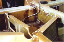
To prepare for the top strake installation, I installed the fuel level sender mounting pad and the fuel filler cap ring in the top strake prior to top strake installation. I feel that this will minimize the amount of debris entering the tank, since it will minimize the amount of glass/foam grinding done with the tank closed.
I then made a form for the sump and glassed the 4 BID sump in place over box sealing tape. I installed the stock fuel line routing with the stock fuel selector valve (after screwing around trying to do some other systems with different valves and line routings - I couldn't get any of them to go together nicely and they didn't seem to have any major advantages, so I trashed them).
After creating a flox "ledge" along the fuselage side just under the strake
top, I floxed the top strake in place. To read the saga of my problems with the result,
check out YAOS (Yet Another Oaf's Story).
After finally finishing the first fuel tank and strake and verifying with a pressure test, I began doing the whole thing over again on the second strake/fuel tank. This one will NOT have the same problems as the first, believe me.
After finishing both strakes, I finished the installation of the outboard diagonals. These have less functionality with the Aerocad strake skins, but I installed one of them nonetheless.
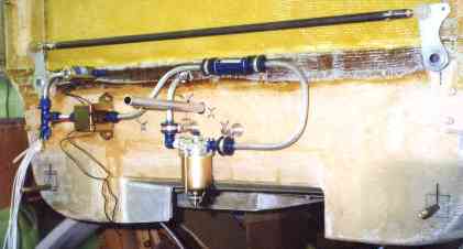 Here you can see the fuel line installation
on the firewall. The 3/8" tubing emerges from the firewall and turns down to
enter the all metal gascolator. The line then curves upward to the
"Earl's" fuel filter and then continues to the electric fuel pump. If the
filter's position before the pump becomes a problem, I will move it to a point downstream
of the pump in the flexible lines going to the mechanical fuel pump, or between the
mechanical fuel pump and the Ellison throttle body.
Here you can see the fuel line installation
on the firewall. The 3/8" tubing emerges from the firewall and turns down to
enter the all metal gascolator. The line then curves upward to the
"Earl's" fuel filter and then continues to the electric fuel pump. If the
filter's position before the pump becomes a problem, I will move it to a point downstream
of the pump in the flexible lines going to the mechanical fuel pump, or between the
mechanical fuel pump and the Ellison throttle body.
The "T" after the pump leads to the main fuel line as well as to the primer solenoid just above the fuel pump. All fuel system parts (fuel pump, solenoid and bracket, gascolator and fuel filter) bolt to the firewall using Adel clamps and/or mounting holes, with nutplates on the inside of the firewall for one-sided installation.
The only thing preventing completion of this chapter involves a very small leak in the left strake/fuel tank. After conducting a leak test with an air conditioning repairman's leak test unit and a small freon injection, I believe that the leak resides in the aluminum tubing near the fuel selector valve. I will conduct further leak tests later.
So, now it's way later. The leak was still there, and I found it again when I added 2.5 gallons of 100LL to the left tank. When parked nose down, the fuel leaked through the L.E. joint of the strake into the passenger compartment, into the map pocket, and down through a water drain hole in the bottom. I cut away a good portion of the left baggage compartment before I found the leak in the L.E. and floxed and glassed it over. I believe the tank is now completely sealed.
The picture above shows an in-line fuel filter PRIOR to the electric fuel pump. This is NOT recommended, so I moved it to a point after the mechanical fuel pump but prior to the Ellison Throttle Body.
[Prev]
[Next]| [Zeitlin's Cozy MKIV Information] [Zeitlin's Cozy MKIV Logbook] [Cozy MKIV Information] |
Copyright © 1997 - 2002, All Rights Reserved, Marc J. Zeitlin
email: marc_zeitlin@alum.mit.edu