[Prev]
[Next]
Cozy MKIV - Chapter 19
Building the Wings, Ailerons, and Wing Attachments
Start Date: July 13, 1996
I decided (after getting a ride in a L.E., getting pumped about finishing this plane,
and talking to Chris Scida) to get the wing quick build kit from AeroCad instead of doing
everything from scratch. With this kit you get: pre-cut foam cores (with 6" longer
ailerons [although Jeff will cut them to the standard length if you want]), molded spars,
instructions, video tapes and two aluminum I-beams for trailing edge layups. The kit runs
around $1.8 K, plus you still need about $600 of stuff from Wicks (or whomever). So, you
end up paying about $1500 more, but I can see that I'll save at least one if not two
months of work.
Anyway, since I will use this kit my descriptions will not match Nat's plans exactly,
but I'll describe what's different, if I can.
Nat has you micro all the Trailing Edge cores together in jigs, layup the shear web,
micro the Leading Edge cores on, and then layup the spar caps.
 First, I sanded the vacuum bagged spars with a belt sander with
medium grit paper to take the glaze off and leave a rough surface for glassing and
microing. I then jigged the spars level on saw-horses and microed the Leading Edge cores
to them, making sure that the level lines stayed vertical. Jeff uses drywall screws to
hold the cores in alignment during cure instead of nails, so I tried this. It worked very
well.
First, I sanded the vacuum bagged spars with a belt sander with
medium grit paper to take the glaze off and leave a rough surface for glassing and
microing. I then jigged the spars level on saw-horses and microed the Leading Edge cores
to them, making sure that the level lines stayed vertical. Jeff uses drywall screws to
hold the cores in alignment during cure instead of nails, so I tried this. It worked very
well.
I then flipped the spar/cores over, leveled them, and microed the Trailing Edge cores
to the back of the spars. Voila, two full days worth of work, and I have wings ready for
the skin layups.
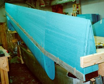
I then jigged the right wing aluminum I-beam (to keep the trailing edge perfectly
straight) and spent a week or so hard-shelling
the bottom surface of the wings to get them perfectly smooth and flat. The trailing edge
sits directly on the I-beam, and the wing skin gets layed up on the beam, over a joggle in
the foam. This creates a perfectly straight trailing edge. Well, almost.
I needed one more NAV antenna (along with the one in the bottom of the fuselage) so I
routed a 1/16" deep channel in the bottom of the right wing (in the hard shell) about
3" from the leading edge. I drilled a shallow angle hole through to the hot-wired
wire tunnel and threaded the RG-58U plenum cable from the antenna hole to the tunnel. Then
I installed the antenna and microed over it.
 Next, I cut the UNI and BID glass for the right bottom wing
skin layup per Nat's plans and layed up the bottom skin on the right wing, peel plying the
trailing edge, rib areas and aileron cutout area. After cure, I trimmed the excess glass
and microed any depressions in the skin as well as the trailing edge. I marked the wing
with the root and tip B.L.'s, and sanded the leading edge smooth for the top surface
overlap.
Next, I cut the UNI and BID glass for the right bottom wing
skin layup per Nat's plans and layed up the bottom skin on the right wing, peel plying the
trailing edge, rib areas and aileron cutout area. After cure, I trimmed the excess glass
and microed any depressions in the skin as well as the trailing edge. I marked the wing
with the root and tip B.L.'s, and sanded the leading edge smooth for the top surface
overlap.
 I flipped the wing over, and then sanded the foam
smooth on the top surface. After hard-shelling the top, I routed the groove in the top
surface for the rudder cable.
I flipped the wing over, and then sanded the foam
smooth on the top surface. After hard-shelling the top, I routed the groove in the top
surface for the rudder cable.
Actually, I routed two grooves - one for the standard cable position, and one for the
concealed belhorn cable position. I installed two runs of nylaflow tubing, since I'm not
sure which version I'll use, and this will allow me to pick and choose. Instead of using
micro to completely fill up the groove in the root area, I used pour foam. THIS IS A
BIG MISTAKE! The pour foam lifts the nylaflow tubing, and it took a while of hacking
at it to get it back in the right place. Oh, well - live and learn. After microing the
tubing in place and finishing the hard-shelling, I sanded the top surface smooth and laid
up the top skin.
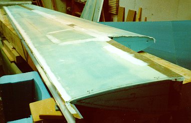
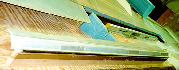
You can see the electrical conduit hole in the front rib, the wing attach bolt access
cutout, the wing attach plate reinforcement layup strips, and the small wooden blocks for
wing leveling all in this one, inclusive picture.
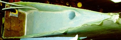 I trimmed the skin and then removed the foam for
the wing root rib areas. I cut out the aileron and cleaned up the aileron attach/rear spar
area. I fabricated all the aileron hinges and sanded the aileron to shape for the A-2,
A-5, A-10, and balance rod pieces. I laid up the front and rear rib areas, the aileron,
and the rear spar/aileron attach area.
I trimmed the skin and then removed the foam for
the wing root rib areas. I cut out the aileron and cleaned up the aileron attach/rear spar
area. I fabricated all the aileron hinges and sanded the aileron to shape for the A-2,
A-5, A-10, and balance rod pieces. I laid up the front and rear rib areas, the aileron,
and the rear spar/aileron attach area.
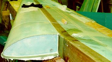
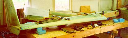
 You can see the aileron and the aileron cutout/rear spar area in the wing
in this image (if you tilt your head a bit to the right). The dark areas are the metal
pieces buried in the aileron for the hinge attach points.
You can see the aileron and the aileron cutout/rear spar area in the wing
in this image (if you tilt your head a bit to the right). The dark areas are the metal
pieces buried in the aileron for the hinge attach points.
I attached the hinges to the wing and the aileron and attached the aileron torque tube
actuation stuff. I used Delrin for the bearings of the torque tube at the wing root,
rather than the recommended phenolic.
After finishing the one wing, I went back and did it all again on the other one.
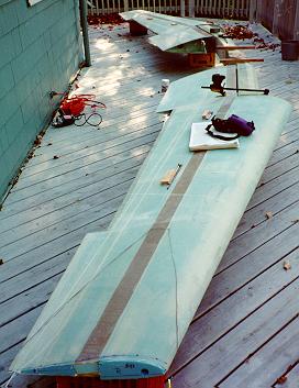 OK, so now I've got these
two wings - the next step is to jig drill the mounting holes to the center spar. I drilled
the #10 pilot holes and the 1/4" guide holes in the center spar. Then I brought all
three parts (center spar and both wings) out onto the deck (the only relatively flat place
I've got with over a 30' span) and set them up on milk crates in their approximate
position.
OK, so now I've got these
two wings - the next step is to jig drill the mounting holes to the center spar. I drilled
the #10 pilot holes and the 1/4" guide holes in the center spar. Then I brought all
three parts (center spar and both wings) out onto the deck (the only relatively flat place
I've got with over a 30' span) and set them up on milk crates in their approximate
position.
Using my "SmartLevel", regular bubble level and water level (1/2"
diameter tygon tubing filled with water) I leveled one wing, butted the center spar up
against it so that all three mounting points were flat and tight, and then did a gross
level of the spar. I then butted the second wing up against the spar, and through a long,
iterative series of levelings and shimmings of all three parts, I finally got everything
level, plumb, and even.
At this point, I very carefully bondoed all three parts together near the drill points.
Using the previously drilled 1/4" pilot holes, I drilled all six holes to 1/4"
and then, using the 5/8" c'bore, drilled them all through. Nat states in the plans
not to let them get too hot - BE CAREFUL - this drilling produces a LOT of heat!! I
needed to rotate between the six holes on a regular basis, and sometimes go away for 10
minutes. I think it took about 2 hours to drill all six holes. Lastly, I bondoed level
boards to the center spar.
At this point, I cut through the bondo, sanded the rest off, and brought all three
parts back inside the basement. I then began to setup for the rest of Chapter 20 - Winglets.
Hiatus Date: November 2, 1996
Hiatus End Date: May 25, 1998
 So, after a year and a half wait and a new house
purchase, I got the spar mounted in the fuselage and readied the wing(s) for attachment. I
made the LWA9 bushings myself, not wanting to give Brock the money. Takes my about 20
minutes per bushing on a Hardinge lathe, so it's a good thing I'm not paying myself here
:-).
So, after a year and a half wait and a new house
purchase, I got the spar mounted in the fuselage and readied the wing(s) for attachment. I
made the LWA9 bushings myself, not wanting to give Brock the money. Takes my about 20
minutes per bushing on a Hardinge lathe, so it's a good thing I'm not paying myself here
:-).
Anyway, I dry fitted the bushings to the right wing and right side of the spar, and
then cut them to length for each appropriate hole. I then supported the wing on my table
behind the spar with all of the bushings inserted, and bolts in the wing bushings. I
shimmed it to be level and even with the spar holes, and then slowly worked it forward.
Every once in a while the fates smile on me, and the bolts slid smoothly into all three
holes in the spar without any banging or forcing on my part - bingo!
After finishing up the strakes on the right side, I rotated the fuselage around and
mounted the left wing in the same manner.
End Date: June 20, 1998
[Prev]
[Next]
Copyright © 1996 - 1998, All Rights Reserved, Marc J. Zeitlin