[Prev][Next]
Cozy MKIV - Chapter 14
Building the Center Section Spar
Start Date: August 26, 1995
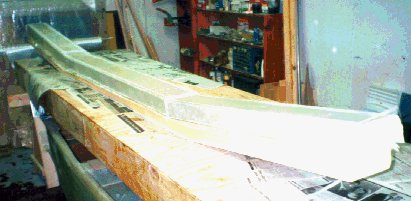
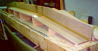 I started out by slicing a 3/4" particle board up into the pieces needed
to construct the main spar jig. With these, shims, 3/4" pine boards, and
a level, I put the jig together on my work table. You can see the jig
here:
I started out by slicing a 3/4" particle board up into the pieces needed
to construct the main spar jig. With these, shims, 3/4" pine boards, and
a level, I put the jig together on my work table. You can see the jig
here:
 Next I cut out all the 3/8" and 1" foam for the spar and hot-glued it in
place in the jigs while I micro'ed all the foam pieces together. Then I
cut the BID and UNI glass for the interior layup. I then cut out the
aluminum wing mount reinforcements and radiused the corners as needed.
I was told that the interior layup would take a LONG time (maybe 8 hours
or so), so I put off doing it until a Saturday. You can see the
micro'ed foam pieces (with a top piece nailed in place for stability)
ready for glassing here:
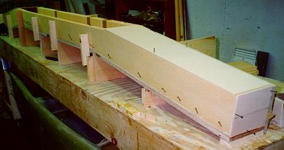
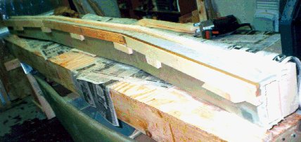
Next I cut out all the 3/8" and 1" foam for the spar and hot-glued it in
place in the jigs while I micro'ed all the foam pieces together. Then I
cut the BID and UNI glass for the interior layup. I then cut out the
aluminum wing mount reinforcements and radiused the corners as needed.
I was told that the interior layup would take a LONG time (maybe 8 hours
or so), so I put off doing it until a Saturday. You can see the
micro'ed foam pieces (with a top piece nailed in place for stability)
ready for glassing here:
Well, in fact it took 2 1/2 weeks for the Saturday (actually a Sunday)
to roll around - I didn't get to glass the interior until October 1. It
did, in fact, take 7 hours, almost on the nose.
First, I micro'ed the left side of the spar, micro-filleted the
horizontal and vertical corners, pre-wetted the 1 BID on saran wrap (as
I did for ALL the subsequent layers of BID or UNI), and then diligently
placed the BID into the spar cavity and smoothed it against the lower
(rear) surface and the vertical sides (top and bottom). Next, I put 1
BID over the end bulkheads lapping 1" onto the three other surfaces, and
then micro'ed the CS6 bulkhead in place. After pressing in nails to
hold it in, I micro-filleted the corners and laid up 1 BID on either
side of the bulkhead, lapping 5" where the LWA metal wing attach piece
would later go.
Next, I glassed the BID and UNI for the LWA's (two outboard and one
inboard). I then repeated the whole process for the right side of the
spar (micro, fillet, glass, bulkhead, glass). After installing the
center section BID as well, I installed the center bulkhead and glassed
1 BID on either side.
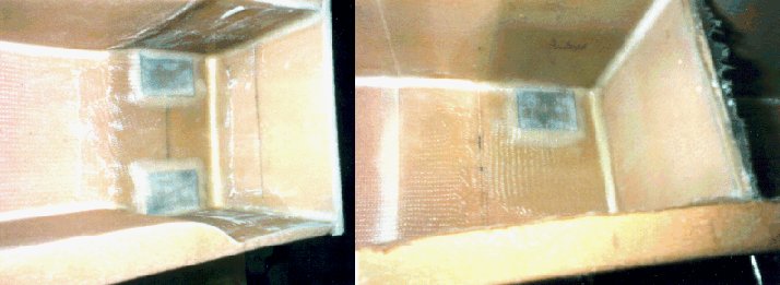
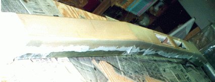
I then floxed all 6 LWA's (1/8" aluminum plates) in place over the
future wing attach bolt positions. I covered these with BID overlapping
1" onto all adjacent surfaces, with flox transitions from the metal.
You can see the LWA installation here:
 After trimming and sanding this layup flush and smooth, I cut the glass
for the inner surface layups of the top (front) foam pieces (45 deg.
BID) and glassed those foam pieces. Next (after trimming), I micro'ed
the cured top pieces onto the spar box.
After trimming and sanding this layup flush and smooth, I cut the glass
for the inner surface layups of the top (front) foam pieces (45 deg.
BID) and glassed those foam pieces. Next (after trimming), I micro'ed
the cured top pieces onto the spar box.
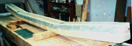
The next step was to cut and sand the spar cap troughs to shape per the
depth templates, as well as create cutouts in the foam for the LWA4's
and LWA5's (Wing metal attach plates). I floxed the LWA4's and LWA5's
in place, and then I layed up the first half of the shear web - 4
plies of UNI glass at 45 deg.
 You can see the first shear web layup here:
 After hot gluing a 1"x2" as a dam
for the spar cap layup, I put in the 23 Layers of 3" glass rovings.
This took about 8 hours. After trimming and sanding, I turned the spar
over, and dammed and layed up the bottom spar cap 17 Layers).
After hot gluing a 1"x2" as a dam
for the spar cap layup, I put in the 23 Layers of 3" glass rovings.
This took about 8 hours. After trimming and sanding, I turned the spar
over, and dammed and layed up the bottom spar cap 17 Layers).
 I cut and micro'ed the shoulder harness attach point block into place in
front of the top spar cap, and then layed up the second half of the shear
web - another 4 UNI plies. When this was semi-cured
(big mistake!!) I floxed the LWA2's and LWA3's in place (more
Wing attach metal plates) and laid up the UNI and BID reinforcing layups
over the LWA's. The next day, I pulled the peel-ply off the reinforcing
layups, and half the layups came with it!!! AAARRRRGGGGHHHH!!!
It turns out that the 2427 epoxy I'm using doesn't like to have stuff
attached to it when it's just gelled; either make sure the layup goes
on while the previous one is still wet, or wait till it cures and then
sand it. I removed the reinforcing layups, as well as 1 of the LWA3's,
and sanded all the areas to reapply those layups. Where I had forcibly
pried the LWA3 off, I had delaminated the second 4 UNI plies of the shear
web, so I had to sand that off and feather the edges for a replacement
4 UNI plies. After re-floxing on the LWA3 and re-applying the
reinforcing layups, everything was copasetic.
I cut and micro'ed the shoulder harness attach point block into place in
front of the top spar cap, and then layed up the second half of the shear
web - another 4 UNI plies. When this was semi-cured
(big mistake!!) I floxed the LWA2's and LWA3's in place (more
Wing attach metal plates) and laid up the UNI and BID reinforcing layups
over the LWA's. The next day, I pulled the peel-ply off the reinforcing
layups, and half the layups came with it!!! AAARRRRGGGGHHHH!!!
It turns out that the 2427 epoxy I'm using doesn't like to have stuff
attached to it when it's just gelled; either make sure the layup goes
on while the previous one is still wet, or wait till it cures and then
sand it. I removed the reinforcing layups, as well as 1 of the LWA3's,
and sanded all the areas to reapply those layups. Where I had forcibly
pried the LWA3 off, I had delaminated the second 4 UNI plies of the shear
web, so I had to sand that off and feather the edges for a replacement
4 UNI plies. After re-floxing on the LWA3 and re-applying the
reinforcing layups, everything was copasetic.
 Next, I prepared the front of the spar by cutting out 5"x13" access
holes and feathering the edges for glass-to-glass bonds. I layed up the
2 UNI plies onto the front of the spar, and made sure that the layup was
pretty rich in epoxy, as it will be exposed to fuel in the fuel
tanks.
Next, I prepared the front of the spar by cutting out 5"x13" access
holes and feathering the edges for glass-to-glass bonds. I layed up the
2 UNI plies onto the front of the spar, and made sure that the layup was
pretty rich in epoxy, as it will be exposed to fuel in the fuel
tanks.
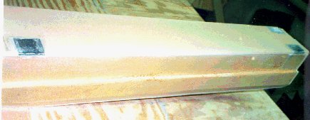
After that cured, I trimmed and sanded all the previous layups, and then
prepared for the last layups by making flox corners on the ends of the
spar, and cutting 2.25" diameter holes out near the tips of the spar.
These (along with the 5"x13" cutouts) are used for access to the wing
attach bolts inside the spar. I layed up 1 BID ply over the ends of the
spar, and micro'ed the holes so that there would be no exposed foam. After
trimming and sanding these layups, I hung the spar up in the basement
against the wall to wait until I have the room to install the spar into
the fuselage in step 10.
On to chapter 9!!!
Hiatus Date: November 8, 1995
Hiatus End Date: May 15, 1998
Well, after a two and a half year wait and the purchase of a new house
with a large garage, I began fitting the spar into the fuselage.
I carefully leveled my fuselage (up on the gear, now!) and then mounted
the canard. [I had my second EAA technical inspector inspection a
couple of weeks ago, done by Paul Adrien, and he suggested that when I
mount the spar to have the canard mounted to use as a level reference].
I then mounted the spar in the rear cutout per the plans. I had to do a
bit of sanding on the front surfaces of the cutouts to get the spar far
enough forward so that there was 1/4" between the rear of the spar and
the rear of the firewall and so that I could ensure the perpendicularity
of the spar to the fuselage centerline. The plans were very good at
describing how to do that.
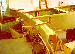 You can see the spar shimmed and jigged in the fuselage in the photo.
After getting the spar shimmed level and square with the rear mounting
faces vertical, I stood about 10 feet in front of the plane right in
front of the nose, and then closed one eye. With the open eye (duh) I
sighted over the canard and lowered my head until each side of the spar
JUST disappeared behind the canard. I had to do a minor amount of
shimming to get the canard and spar dead nuts level with each other - I
could clearly note 1/10 degree over the 12 feet, and that represents
about the limit of the levels I've got.
I made two EM-2's from aluminum. I then floxed and glassed them in
place over the lower engine mount points with 1 BID.
So, after getting everything in place, I marked all my shims, sanded all
the relevant areas, and then floxed the spar in place. I rechecked all
the level, squareness, and canard parallelism again, and let it cure. I
then glassed all the 2 and 3 BID tapes to hold the spar in. At that
point it occurred to me that at no point did I consider the HEIGHT of
the spar with respect to the fuselage - the plans did not talk about
that issue. I poked around on the large sheets and found that the top
of the spar was supposed to be at WL 22, exactly 1" down from the top of
the main longeron at WL 23. So, out with the trusty ruler to find out
where the heck my spar ended up. Arrgh. It's at 21 5/8". My cutout
was a bit large, I guess, and instead of shimming it up flush with the
top, I left it flush with the bottom.
I will NOT be cutting out my spar to raise it the 3/8" - in my
opinion this is not aerodynamically important. However, it does have
implications for attaching the strakes, which are supposed to be at WL
17.4. In my case, I will have to adjust that downward to WL 17.025 (WL
17, since I can't measure the 0.025 with a felt tip pen :-) ). My
fuselage side cutouts for baggage compartment access will also have to
be 3/8" lower. I did, however, want to bring this issue to everyone's
attention so that they made sure to put the spar at the right level to
save themselves the aggravation of having to adjust the strake height
later on.
Finish Date: May 23, 1998
[Prev][Next]
Copyright © 1995 - 1998, All Rights Reserved, Marc J. Zeitlin