[Prev][Next]
Cozy MKIV - Chapter 9 (Section 6)
Axles, Wheels and Brakes
Start Date: February 3, 1996
After receiving the MATCO Wheels and Brakes (which I ordered through
Infinity Aerospace)
and figuring out just how the brake mounting plate worked, I positioned
and fitted the axles to the strut ends. (The MATCO triple puck brakes
have over 50% more energy absorption capability than the Cleveland
brakes recommended in the plans, and are slightly narrower as well. Nat
doesn't like them, but they're used on the Velocity and other aircraft).
I then marked the far wall (~16 feet away) with markings exactly
opposite the axle mounting points. I made marks at appropriate points
to align the axles for toe-in.
I cut, ground and sanded the strut ends to create clearance for the
triple puck calipers, trying to align the cutouts so as to leave as much
material as possible on the strut, have as much strength as possible,
and still leave the caliper approximately vertical so that I could bleed
it easily later on.
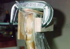 I then made two 1/16" aluminum backing plates. I glassed 3 BID around
the strut end, and then floxed the backing plate in place. I put a flox
pad on the outside of the strut and clamped the flox, BID, strut, BID,
flox, and backing plate between two flat wooden blocks. I used a
combination of Eric Westland's and Norm Balog's technique to align the
outer flox pads. I taped slits onto the end of the 20" nose gear torque
tube and then used this tube to accurately point the wooden block at the
inner wall markings (for toe-in). I adjusted the clamps until the blocks
were aligned, and then let it cure.
I then made two 1/16" aluminum backing plates. I glassed 3 BID around
the strut end, and then floxed the backing plate in place. I put a flox
pad on the outside of the strut and clamped the flox, BID, strut, BID,
flox, and backing plate between two flat wooden blocks. I used a
combination of Eric Westland's and Norm Balog's technique to align the
outer flox pads. I taped slits onto the end of the 20" nose gear torque
tube and then used this tube to accurately point the wooden block at the
inner wall markings (for toe-in). I adjusted the clamps until the blocks
were aligned, and then let it cure.
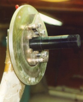 After trimming and sanding the layup, I clamped the axles in place and
drilled out the 1/4" axle mounting holes through the strut and the
backing plate. I test mounted the axles with the brake calipers and
adjusted the strut clearances. Then I built up the main wheels and
tires and test mounted everything in place on the axles.
After trimming and sanding the layup, I clamped the axles in place and
drilled out the 1/4" axle mounting holes through the strut and the
backing plate. I test mounted the axles with the brake calipers and
adjusted the strut clearances. Then I built up the main wheels and
tires and test mounted everything in place on the axles.
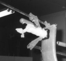
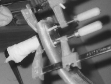
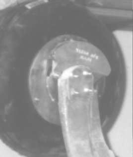
I've got a few pictures (B&W) of Mark and Nadine Parmalee's installation
of their MATCO gear as well. It's slightly different than mine, but the
basic idea is the same:
 After ensuring that everything fit and that the nylaflow lines reached
through the straws in the strut trailing edge to the brake fittings, I
removed the wheels, brakes, and strut, and stored them all away.
After ensuring that everything fit and that the nylaflow lines reached
through the straws in the strut trailing edge to the brake fittings, I
removed the wheels, brakes, and strut, and stored them all away.
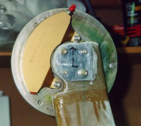
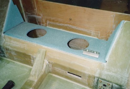
The plans call for the nylaflow brake tubing to go through holes in the
landing gear bulkhead to fittings inside the fuselage. I felt that this
would make the Landing Gear Strut more difficult to remove. The Matco brakes
had also come with a larger diameter brake tubing and fittings. In
order to use these, and to ensure that the landing gear could be removed
completely, I made an aluminum manifold with 1/8" pipe threads on either
side. I floxed this manifold into the front landing gear bulkhead so
that there would be permanent 90 degree elbows for the brake lines both
inside the fuselage and inside the landing gear well. Looking back on
this now, it seems a bit superfluous, but it will make removing the
landing gear brake lines somewhat easier. You can see the manifold here
prior to floxing, along with the landing gear box cover and sides prior
to final glassing:
After glassing that, the long journey through
Chapter 9 was over. On to
Chapter 13!
End Date: February 11, 1996
[Prev][Next]
Copyright © 1995 - 2005, All Rights Reserved, Marc J. Zeitlin